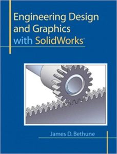
Engineering Design and Graphics with SolidWorks
Engineering Design and Graphics with SolidWorks
Engineering Design and Graphics with SolidWorks shows students how to use SolidWorks to create engineering drawings and designs. The book focuses on the creation of engineering drawings, including dimensions and tolerances and the use of standard parts and tools. Each chapter contains step-by-step sample problems that show students how to apply the concepts presented in the chapter. This book teaches users how to:
- Set up drawings and use the SolidWorks Sketch tools to create 2D drawings that can be extruded into solid 3D models.
- Use the Feature tools to create and modify 3D solid models.
- Create views using third-angle projection.
- Fashion assembly drawings using the Mate tool.
- Produce and design with threads and fasteners (both ANSI inch and ANSI metric threads are covered).
- Use the Design Library to create bearing drawings.
- Draw cams and springs, add hubs and keyways to cams, and insert the cams into assembly drawings
You can also read CSWE – Certified SolidWorks Expert Preparation Materials
Engineering Design and Graphics with SolidWorks Product details
- Paperback: 552 pages
- Publisher: Peachpit Press; 1 edition (May 21, 2009)
- Language: English
- ISBN-10: 0135024293
- ISBN-13: 978-0135024294
- Product Dimensions: 8.4 x 0.9 x 10.7 inches
- Shipping Weight: 2.5 pounds
Engineering Design and Graphics with SolidWorks Content
- Introduction
![Engineering Design and Graphics with SolidWorks]()
- Getting Started
- Sketch Entities and Tools
- Features
- Orthographic Views
- Assemblies
- Threads and Fasteners
- Dimensioning
- Tolerances
- Gears Pulleys and Chains
- Bearings and Fit Tolerances
- Cams and Springs
- Appendix
The first devices created to assist in creating engineering drawings that I remember were introduced in the mid-sixties.The devices were plotters used to draw loft lines—more Specifically, the contour of an aircraft wing. Up to that time.
There was resistance at that time to the “new” technology. Many drafts persons simply refused to learn the new systems that they saw as slow, cumbersome, and impersonal. There was a great deal of pride among drafts persons in creating accurate, carefully crafted engineering drawing, and the new machine seemed to disregard that skill.


Comments are closed.